IFK-Facade collector
1. TECHNICAL DESCRIPTION
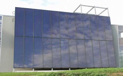
The collector facade is a framework construction that is made up of several prefabricated solar thermal collectors. The collector’s surface can be integrated into the building's facade, regardless of design, without rear thermal ventilation.
Simple and affordable assembly:
To make assembly both simple and affordable (finished collectors), a new assembly
system was developed that no longer requires the individual parts of the collector
to be assembled on-site. The collector is attached to the wall with a special
supporting frame. The first collector is placed on this frame, the frame is
hooked into the slot and attached to the wall. Using this system, any number
of panels can be mounted above and next to one another.
Connecting the absorbers to one another:
The absorbers are connected to one another during assembly using stainless steel
corrugated pipes. The collector is designed in such a way that each individual
collector module can be accessed independently for repair work without having
to take apart the entire collector panel.
Optical features:
There are matching two strips that hold the glass in place: the lower one secures
the glass and the top one is only for decoration. They come in all RAL colours
and are mounted at the very end. One special advantage is that all of the glass
cover strips are the same width.
2. TECHNICAL DESCRIPTION OF THE COMPONENTS
2.1 Module dimensions
| Max. size: | 2000 x 5000 |
| Height: | 120 mm |
The size of the modules is also tailored to individual customer needs.
Installation angle: 80-90°, other installation angles possible following
technical testing.
Thermally separated aluminum frame.
Wooden or aluminium rear panel with diffusion barrier, optional fire protection (Promat).
2.2 Absorbers
Full-face absorbers with GREENdesign, header tubes and register tubes are hard-soldered and welded to the absorber by means of ultrasonics.
| Header tubes: | 22x0,8 mm |
| Manifolds: | 8x0,5 mm |
| Copper sheet: | vacuum-coated 0,2 mm |
| Connections: | flat-sealing DM22-1" screw couplings |
2.3 Cover
4 mm low-iron solar glass, tempered
| Glass sizes | up to a maximum of 1000 x 2000 x 6 mm standard (larger sizes only following testing by a structural engineer). |
| Glass thicknesses: | Standard 4 mm, other glass thicknesses conditional upon legal requirements. |
| Transmission: | >90,8% +/- 2% |
| Pane sealant: | UV-resistant EPDM sealant-Shore 70 |
The thickness of the glass selected is dependent on the wind load and has to be calculated individually for each system by a local structural engineer (calculations in accordance with ÖNORM B 3721, etc.).
2.4 Insulation
50 mm thick mineral wool board or 9 mm thick edge insulation with black glass fleece (with no gas emissions).
| Thermal conductivity | 0,045 W/mK |
| Gross density | 50 - 80 kg/m³ |
2.5 Other
The plastic clips for the header pipes are made of black plastic that is reinforced
with fibreglass.
They create a thermal separation to the tray.
Type plate: UV-resistant, weatherproof silver polyester sticker.
Attachment: The design of the attachments depends on what the wall is made of, taking into account the maximum wind load set by the standard depending on the height of the building.
The local structural engineer must ensure proper design of the wall mounts and must select the glass thickness which is initiated by the developer..
3. TECHNICAL DATA
| Weight [kg]: | 30 kg/m>2 |
| Coating: |
highly selective absorber coating |
| Absorption | 95,0 % +/- 2% |
| Emission | 5,0 % +/- 2,0 % |
|
Other data: |
|
| Stagnation temperature: | 180o C plus temperature ambient |
| Max. operating pressure: | 10 bar |
| Design approval No: | TÜV 02 - 328 - 083 |
| Heat transfer medium: | Propylene glycol-water mixture |